 The
The Non Model-Specific Tips
Advice and guidance for the maintenance of Armstrong Siddeley cars. If you have other technical advice for Armstrong Siddeley owners you would like to share here, please contact web@siddeley.org
Please note, technical tips are given by individual members and ASOC Ltd does not warranty the accuracy of them or endorse them in any way.
More tips can be found by using the links to the right.
AC Fuel Pump - How it Works and Servicing
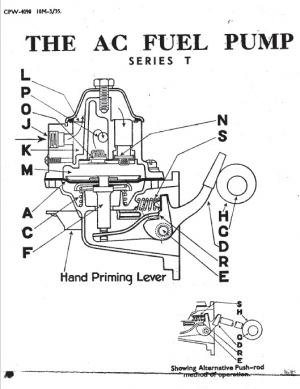 By revolving shaft (G) the excentric (H) will lift rocker arm (D), which is pivoted at (E) and which pulls the pull rod (F), together with the diaphragm (A) downward against spring pressure (C) thus creating a vacuum in pump chamber (M). Fuel from the rear tank will enter at (J) into sediment chamber (K) and through filter gauze (L) and suction valve (N) into pump chamber (M). On the return stroke, spring pressure (C) pushes diaphragm (A) upward forcing fuel from the chamber (M) through pressure valve (O) and opening (P) into the carburetter.
When the carburetter bowl is filled the float chamber will shut off the inlet needle valve, thus creating pressure in the pump chamber (M). This pressure will hold diaphragm (A) downward against the spring pressure (C) and it will remain in this position until the carburetter requires further fuel and the needle valve opens.
The rocker arm (D) is in two pieces, the outer operating the inner one by making contact at (R) and the movement of th eccentric (H) is absorbed by this break when fuel is not required. Spring (S) is merely for the purpose of keeping the rocker arm (D) in constant contact with the eccentric (H) to eliminate noise.
Service Hints
Service on the AC Fuel Pump is available through Authorised AC Service Stations, who are prepared with the parts and fixtures for preparing all types of pump. There are some service operations on this fuel pump that can, if necessary, be done without referring to the service station. In some instances trouble is attributed to the fuel pump which in reality is caused by some other condition such as slightly loose connections or choked petrol pipes. These should be carefully watched to avoid the needless attention to fuel pumps.
Lack of fuel at the carburetter
| Cause | Remedy |
| Petrol tank empty | Refil |
| Leaky tubing or connections | Replace tubing if leaky and tighten all pipe connections at the fuel pump and petrol tank |
| Bent or kinked tubing | Replace tubing |
| Filter cover loose | Tighten nut, making certain that cork gasket lies flat in its seat and is not broken or unduly compressed |
| Dirty filter screen Remove filter cover and clean the screen. | Make certain that cork gasketis properly seated when reassembling and that the fibre washer is under head of screw. |
CAUTION: Do not disassemble the pump body.
NOTE: Sometimes there appears to be a leak at the diaphragm, whereas the leak actually exists at one of the pipe fittings and the fuel has run down the pump to the diaphragm flange, appearing to originate there.
Flooding of Carburetter
Carburetter needle valve not seating. Check carburetter for proper adjustment also thoroughly clean out float chamber if any dirt is present.
Note to Service Stations and Garages
After removal of the upper cover of any type of AC Fuel Pump it is important that the cover should only be replaces while the pump pull rod is at the top of its stroke. This is to ensure sufficient flexing of the diaphragm to allow its normal working movement
Editorial Note:
When reassembling pump onto engine, ensure that great care is taken to locate the rocker arm (D) above the eccentric (H). (In my experience it is very easy to get it wrong.)
Reducing the slop in windscreen wipers - Supplied by Keith Dewhurst
The Lucas-made rack driven systems often acquire a large amount of slop in them with the wipers running into or off the edges of the screen. Each wiper is driven by a gearwheel at the base of the wiper spindle turned by a spiral wound cable being pulled backwards and forwards across the gearwheel. If, with the system in the normal off position, you remove the wiper blades and arms and mark the 12 o’clock position of each with paint it is possible to turn the gearwheel round by 180 degrees so it is working on a hopefully unused part (unless someone has already done this in the past).
To do this you will need to pull the driving cable back just clear of both gearwheels, you can tell when you have cleared them when they stop rotating as you pull the cable back, reposition them by 180 degrees and then push back the drive cable fully home. Check each spindle now has its mark at 6 o’clock and if not have another go. To enable the cable to move in and out you will have to do some freeing up in the area of the wiper motor. You can either free the motor from it mounting and electrical connections and then undue the hexagonal gland nut where the cable outer enters the motor and pull the whole motor with inner drive cable attached backwards away from the drive cable outer, or, and I prefer this way, release the drive cable entirely from the motor. To do this you will need to remove the pressed alloy cover on the side of the motor to expose the drive mechanism and free the cable from this mechanism. The cable is held in place by the cover and with the cover removed will come off its drive peg sideways if you ease the gland and locknut holding the drive cable outer out of there housing. You can now move the whole drive cable away from the motor and slide the inner towards you and then back in as before. Depending on your exact set up it may be possible to also rotate the drive cable through 180 degrees to also have this work on an unused portion. This is a good time to fully extract the cable and lubricate it and the driving mechanisms in the wiper motor.
Finally when reassembling, have a look at the brass screw and circulator lock collar which take up any end float in the motor armature. This exits on the side of the motor body in the area of the cable drive. It is adjustable and any excess end float will also cause slop in the mechanism. Do not over tighten however, as to do so will load up the motor possibly leading to electrical failure. I usually set these with everything assembled and the motor running.
Making new old stock gaskets fit - Supplied by Keith Dewhurst
I am sure many of us have been delighted to find that bargain gasket set that fits our car at either an autojumble or on eBay. However, more than once I have found that my lovely new cork rocker cover gasket or thick paper sump gasket apparently has been made for a 90% replica of my engine, or in other words it has shrunk!! Trying to pull it in to shape and force it to fit usually results in the gasket tearing apart.
Here is my tip. A day or so before you want to use the gasket try it for size. If it is too small then put it to soak in some cold water in the bottom of the bath! Often after just a short soaking the gasket will have expanded back to normal size and once dried off retains this size and can be used in the normal way. By the way, if you like or wish to use a gasket sealer then I have found Wellseal to be the best of products.
Flushing the cooling system - applies to 346/234/236/16/18 and more models - Supplied by Keith Dewhurst
After a hot summer many owners may be worried about the effectiveness of their car's cooling system and may be considering giving it a good flush through before winter. This is a very good thing to do, but can lead to worse cooling if not done correctly.
A partially blocked, but otherwise good, radiator can often be recovered by having it rodded out by a radiator specialist. The bottom tank and sometimes both tanks are removed, and then each tube cleared of rusty debris by having a thin rod pushed through it. There is of course the danger that this process will damage a tube, or remove rust that was sealing a poetntial leak, and the operative cannot be blamed if this occurs. However, in many instances radiators that were unserviceable can be made good in this way.
Greasy deposits within the radiator can significantly reduce cooling capacity. A good flushing agent or soak in builders acid can often remove this.
Changing main bearing shells with the crankshaft still in the engine and the engine in the car - applies to 346/234/236/16/18 and many many more engines - Supplied by Keith Dewhurst
Not all owners with generally good practical skills are aware of an age old technique for fitting new main bearing shells in to an engine in situ. With the sump off and everything exposed, it is easy enough to detach each big end shell caps and push up the conrod and piston enough to extract the top part of the shell bearing and replace it, but clearly the same is not true for the main bearings. A simple technique however, can make changing the mains just as easy.
Slacken off each main bearing shell just slightly. I like to take them back a bit one buy one and then tighten them up to just hand tight. This will allow the crank to settle a bit without putting it under undue strain. Completely remove the main bearing cap of the bearing you wish to first replace. I usually start at the front. When removing a cap make sure you note the orientation of the cap as the shell bearing carrying surfaces have been line bored with the caps in place. With the cap off, observe which side of the casting and shell on the top half has the little tab in the recess, that locates the shell and prevents it moving. Turn the crank until the oil gallery hole is visible and select a split pin (of the type you would use to lock a nut for example) that easily slides in to the oil hole, but whose head is of a reasonable size. With a small hammer or pliers, reshape the looped head to collapse the hole and make the pin into a T shape. The cross bar of the T being the flattened pin head. The object is that the height of the flattened head should be no more than the thickness of a shell, sometimes it is best to actually bend the head of the flattened pin to make it an inverted capital L. Place the pin in the oil hole and hold it there whilst rotating the crank so that the flattened pin head bears on the side of the upper shell opposite the side with the locating tab. Continue to wind the crank round and the split pin head will push the upper half of the shell around the crank ahead of it until the shell is now at the bottom of the crank and can be removed. Being made of very soft material the split pin will not damage the shell backing or cast housing.
Refitting is the reverse procedure. Place the shell correctly orientated for its locating tab on the bottom of the crank. Rotate the crank a little (now in the opposite direction) and the shell will usually be dragged slightly in to the upper half. if needed give it a little encouragement with your hand to get it stated. Again align your modified split pin in the oil hole and wind the shell fully in to the upper half of the bearing. Fit a new shell to the bottom cap, and refit this, ensuring correct orientation for locating the shell, and tighten up hand tight at this stage. Work through all the bearings in this way and then go back and tighten each nut to the correct torque.
When fitting new shells always liberally coat them in lubricant so that when the engine is fired up there is no metal-on-metal wear taking place as the car oil pump takes its time to get the sump oil through. I like to use STP engine oil additive or similar for this.
Main bearing and bigend caps need to be locked in place. This is usually achieved by either self locking nuts or castlelated nuts and split pins. Always use new split pins where this methodology is used and, if possible, new high-tensile steel self-locking nuts. If no new correct self locking nuts can be founds and the original appear in good condition, then I have reused these using an appropriate lock and seal thread solution.
Whilst the bigends are exposed it is possible to accurately measure the crankshaft diameter with a micrometer and compare this with the specification in the technical section of your car's manual. Take account of any earlier crank regrinds which will be indicated on the rear of the shell bearing. For example 10 thou undersize. There will be an upper and lower limit in the manual. As most shells were made of relatively soft material when compared to the material the crank is made off, there is a good chance that your crank will be within spec. and new shells will return it to good as new condition. However, as these cars are now getting to be quite an age you can be sure of nothing. I even heard of an 18hp that had its big ends wrapped in shim and then the caps tighten back up. For a few miles all was quiet and oil pressure was good, but this did not last and when stripped and examined a terrible mess was found. It is just about possible to measure the mains too, but tricky as only half of the crank is available to get the micrometer across. Both main and bigend bearing surfaces can, by the way, wear oval and often the rear main has tapered wear due to carrying the weight of the flywheel etc.
Whilst doing this work you should also measure crankshaft end float and fit new thrust washers to the crank to bring this in to manufacture's specification.
Sub Menu
Downloads
Login